Speed Regulator (TRIAC)


TRIAC Basics
The TRIAC is a component that is effectively based on the thyristor. It provides AC switching for electrical systems. Like the thyristor, the TRIACs are used in many electrical switching applications. They find particular use for circuits in light dimmers,fan speed regulators, etc., where they enable both halves of the AC cycle to be used. This makes them more efficient in terms of the usage of the power available. While it is possible to use two thyristors back to back, this is not always cost effective for low cost and relatively low power applications.
It is possible to view the operation of a TRIAC in terms of two thyristors placed back to back.


TRIAC equivalent as two thyristors

One of the drawbacks of the TRIAC is that it does not switch symmetrically. It will often have an offset, switching at different gate voltages for each half of the cycle. This creates additional harmonics which is not good for EMC performance and also provides an imbalance in the system
In order to improve the switching of the current waveform and ensure it is more symmetrical is to use a device external to the TRIAC to time the triggering pulse. A DIAC placed in series with the gate is the normal method of achieving this.

DIAC and TRIAC connected together


Basic Circuit:

This is the circuit diagram of the simplest lamp dimmer or fan regulator.The circuit is based on the principle of power control using a Triac.The circuit works by varying the firing angle of the Triac . Resistors R1 ,R2 and capacitor C2 are associated with this. The firing angle can be varied by varying the value of any of these components. Here R1 is selected as the variable element . By varying the value of R1 the firing angle of Triac changes (i.e. how much time should Triac conduct) changes. This directly varies the load power, since load is driven by Triac. The firing pulses are given to the gate of Triac T1 using Diac D1. 
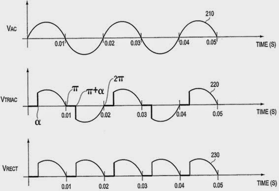
The most basic wavefor(i.e ignoring all losses and harmonics) is shown below.


The waveform shown below demonstrates the output voltage of TRIAC before and after rectification.
Alpha is firinf angel of thyristers.


From the two figures shown below  we can see the output waveform by changing firing angel. In the first figure  the output will be half power of the input power.
In the second figure as firing angel is zero ,therefore output power will be same as input.


The Thing


There is a diaphram in the eye of eagle which get vibrated when sound wave fall on it . It consisted of a tiny capacitive membrane connected to a small quarter-wavelength antenna; it had no power supply or active electronic components. The device became active only when a radio signal of the correct frequency was sent to the device from an external transmitter. 


Sound waves caused the membrane to vibrate, which varied the capacitance of the circuit.When capacitance get changed , operating frequency get changed.When this changed frequency supply reached Antenna circuit, different EM wave is produced which get modulated with incoming EM wave and is get re-transmitted by the Thing. A receiver demodulated the signal so that sound picked up by the microphone could be heard, just as an ordinary radio receiver demodulates radio signals and outputs sound.

Q Factor


The Q, quality factor, of a resonant circuit is a measure of the goodness or quality of a resonant circuit. A higher value for this figure of merit correspondes to a more narrow bandwith, which is desirable in many applications. More formally, Q is the ration of power stored to power dissipated in the circuit reactance and resistance.  


Series Resonance

The resonance of a series RLC circuit occurs when the inductive and capacitive reactances are equal in magnitude but cancel each other because they are 180 degrees apart in phase. The sharp minimum in impedance which occurs is useful in tuning applications. The sharpness of the minimum depends on the value of R and is characterized by the "Q" of the circuit.

The frequency response of the circuits current magnitude above, relates to the “sharpness” of the resonance in a series resonance circuit. The sharpness of the peak is measured quantitatively and is called the Quality factor, Q of the circuit. The quality factor relates the maximum or peak energy stored in the circuit (the reactance) to the energy dissipated (the resistance) during each cycle of oscillation meaning that it is a ratio of resonant frequency to bandwidth and the higher the circuit Q, the smaller the bandwidth. 


Parallel Resonance
The Q-factor of a parallel resonance circuit is the inverse of the expression for the Q-factor of the series circuit. Also in series resonance circuits the Q-factor gives the voltage magnification of the circuit, whereas in a parallel circuit it gives the current magnification.
The selectivity or Q-factor for a parallel resonance circuit is generally defined as the ratio of the circulating branch currents to the supply current and is given as: 


The Q-factor of a parallel resonance circuit is the inverse of the expression for the Q-factor of the series circuit. Also in series resonance circuits the Q-factor gives the voltage magnification of the circuit, whereas in a parallel circuit it gives the current magnification


Resonant circuits are used to respond selectively to signals of a given frequency while discriminating against signals of different frequencies. If the response of the circuit is more narrowly peaked around the chosen frequency, we say that the circuit has higher selectivity. A quality factor Q, is a measure of that selectivity, and we speak of a circuit having a high Q if it is more narrowly selective. 
An example of the application of resonant circuits is the selection of AM radio stations by the radio receiver. The selectivity of the tuning must be high enough to discriminate strongly against stations above and below in carrier frequency, but not so high as to discriminate against the "sidebands" created by the imposition of the signal by amplitude modulation. 

Consider a circuit where R, L and C are all in parallel. The lower the parallel resistance, the more effect it will have in damping the circuit and thus the lower the Q.

Radar


A radar system has a transmitter that emits radio waves called radar signals in predetermined directions. When these come into contact with an object they are usually reflected or scattered in many directions. Radar signals are reflected especially well by materials of considerable electrical conductivityespecially by most metals, by sea water and by wet lands. The radar signals that are reflected back towards the transmitter are the desirable ones that make radar work. If the object is moving either toward or away from the transmitter, there is a slight equivalent change in the frequency of the radio waves, caused by the Doppler effect.

If electromagnetic waves traveling through one material meet another, having a very different dielectric constant or diamagnetic constant from the first, the waves will reflect or scatter or refract  from the boundary between the materials. This means that a solid object in air or in a vacuum, or a significant change in atomic density between the object and what is surrounding it, will usually scatter radio waves from its surface.
Radar receivers are usually, but not always, in the same location as the transmitter. Although the reflected radar signals captured by the receiving antenna are usually very weak, they can be strengthened by electronic amplifiers.

There are basically two types of radar:

1) Primary radar
2) Secondary radar

Primary radar has lots of limitations. It works best with large all-metal aircraft, not so well on small, composite aircraft, and not at all with some of the new "stealth" technology. Its range is limited by terrain and precipitation. It's rather indiscriminite about what it detects: airplanes, trucks, hills, trees. And it only reports a target's  and range, not its altitude (only 2D).

Secondary radar was invented to overcome these limitations. It depends on a transponder in the aircraft to respond to interrogations (type of signal) from the ground station. Depending on the type of interrogation, the transponder sends back an identification code  or altitude information.


Radar ground stations:

 It consist of three separate antennas. The biggest  one is the primary radar antenna, which looks like a parabolic dish that goes round and round . This antenna transmits powerful pulses and then listens for echoes. It is used to detect aircraft skin paint and also can detect weather to some degree. 
The second ground station antenna, called the directional antenna, is used to send interrogations to airborne transponders and to receive replies from those transponders, providing secondary radar capability. It is a bar-shaped  that is usually perched atop the primary radar antenna and rotates along with it. It's called directional because, like the primary radar antenna, it is designed to beam the interrogations and to receive the replies only from the direction it is pointed. 
However, the directional antenna is less than perfectly directional. To design a perfectly directional antenna, we have to make it infinitely large and thus not practical . Real-world directional antennas have weaker side lobes in addition to the main lobe. The side lobes are too weak to be a problem for distant aircraft, but for aircraft close to the antenna site they are a big problem. Unless something was done about them, the side lobes would cause a close-in aircraft to show up as three or four different targets on the controller's screen, causing  confusion.

Side lobe supression:

That's where the third antenna comes in. It's called the omnidirectional antenna because it radiates equally in all directions. Every time the directional antenna sends out an interrogation (which consists of a pair of pulses), the omnidirectional antenna sends out its own pulse . The signal from the omnidirectional antenna is designed to be much weaker than the main lobe of the directional antenna, but stronger than its side lobes. 

When the transponder receives an interrogation, it compares the strength of the three pulses it receives and according to the strength of the signals it provides information.