Communication Channels


The medium by which information is transmitted is known as a communication channel. Some of the common communication channels are fiber optic cable, coaxial cable, satellite and microwave. The transfer of data takes place in the form of analog signals and the transfer of data is measured in the form of bandwidth, the higher the bandwidth the more the data that will be transferred.

Kinds of Communication Channel:

Communication channels are divided in two categories, namely guided media and unguided media.

Guided Media

In this category the communication device is attached to each other directly with cables. The data signals are restricted to a cabling platform and thus they are also known as bounded media. Generally the guided media is called LAN. Some kinds of guided media are coaxial cable, twisted pair wire and fiber optic cable.
1) Twisted Pair Cable - It is the most common used communication media and used in LAN (local area network) for transfer of data between various computers. They are also used in landline telephones to transfer data signals and voice. They are made from a pair of copper wire. They are covered with insulating materials like plastic. The transmission of data takes place at a speed of 9600 bits/second within a distance of 100 meters.
2) Coaxial Cable - They are also known as coaxes and carries signals with high frequency range. They are made from a single copper wire. They are also used in telephone lines. The bandwidth is 80 times more than twisted pair cable. They are also used in LAN.
3) Fiber Optic Cable - They use light to transfer data. The data is transferred at a very high speed of billions bit/second. They are highly used by cable operators, telephone, and broadband internet companies. They are made from glass and is as thin as the human hair. They are coated with plastic also known as jacket.

Unguided Media

In this form the data is transferred in the form of waves. This means that they do not travel along a specific path. It is also known as unbounded media. Data can be transferred all over the globe. Kinds of unguided media are microwave, cellular radio, radio broadcast and satellite.
1) Microwaves- In this kind the data is transferred via air. The waves travel in a straight line. The data is received and transferred via microwave stations. The speed at which data is transferred is 150 Mbps. They are widely used by telephone and cable companies.
2) Satellite- The signals are received from earth stations. Devices like GPS and PDAs also receive signals from these earth based stations. These satellites are located at a distance of 22300 miles above the earth. The process of transferring and receiving data takes place within few seconds. The data is transferred at a speed of 1 Gbps. They are used for purposes like weather forecast, military communication, radio transmission, satellite TV , data transmission, etc.
3) Cellular Radio- they are used for communication via mobile. High frequency radio waves are used for the transmission of data. You can receive and make calls and also access the internet .

4) Radio Broadcasting- Data is transferred and received via radio signals in the air. The transmission takes place for a long distance across cities or countries. The data is received and transferred via a transmitter. The speed at which data travels is 54 Mbps.

Conductive Polymers


Conductive polymers  are organic polymers that conduct electricity.Such compounds may have metallic conductivity or can be semiconductors . The biggest advantage of conductive polymers is their processability, mainly by dispersion.
A dispersion is a phenomenon  in which particles are dispersed in a continuous phase of a different state.
Conductive polymers are generally not thermoplastics , i.e. , they are not thermoformable. But, like insulating polymers, they are organic materials. They can offer high electrical conductivity but do not show similar mechanical properties to other commercially available polymers. The electrical properties can be fine-tuned using the methods of organic synthesis  and by advanced dispersion techniques.

Thermoplastics:

The polymer chains associate through intermolecular forces , which weaken rapidly with increased temperature, yielding a viscous liquid. Thus, thermoplastics may be reshaped by heating and are typically used to produce parts by various polymer processing techniques.
Organic synthesis is a special branch of chemical synthesis and is concerned with the construction of organic compounds via organic reactions .
Each step of a synthesis involves a chemical reaction, and reagents and conditions for each of these reactions must be designed to give an adequate yield of pure product.
The conductivity of such polymers is the result of several processes. For example, in traditional polymers such as polyethylenes, the valence electrons are bound in sp3 hybridized covalent bonds . Such "sigma-bonding electrons" have low mobility and do not contribute to the electrical conductivity of the material. However, in conjugated materials, the situation is completely different. Conducting polymers have backbones of contiguous sp 2 hybridized carbon centers. One valence electron on each center resides in a p z orbital, which is orthogonal to the other three sigma-bonds. All the pz orbitals combine with each other to a molecule wide delocalized set of orbitals. The electrons in these delocalized orbitals have high mobility when the material is "doped" by oxidation, which removes some of these delocalized electrons. Thus, the conjugated p-orbitals form a one-dimensional electronic band , and the electrons within this band become mobile when it is partially emptied.

Electrophoretic


In the simplest implementation of an electrophoretic display, titanium dioxide (titania) particles approximately one micrometer in diameter are dispersed in a hydrocarbon oil. A dark-colored dye is also added to the oil, along with surfactants and charging agents that cause the particles to take on an electric charge. This mixture is placed between two parallel, conductive plates separated by a gap of 10 to 100 micrometres . When a voltage is applied across the two plates, the particles migrate electrophoretically  to the plate that bears the opposite charge from that on the particles. When the particles are located at the front (viewing) side of the display, it appears white, because light is scattered back to the viewer by the high-index titania particles. When the particles are located at the rear side of the display, it appears dark, because the incident light is absorbed by the colored dye. If the rear electrode is divided into a number of small picture elements (pixels), then an image can be formed by applying the appropriate voltage to each region of the display to create a pattern of reflecting and absorbing regions.


Electrophoretic displays are considered prime examples of the electronic paper category, because of their paper-like appearance and low power consumption.

Smart Glass


Recent advancements in modified porous nano-crystalline films have enabled the creation of electrochromic display or smart glass. This can be of various types.

Single Substrate Display Structure:

The single substrate display structure consists of several stacked porous layers printed on top of each other on a substrate modified with a transparent conductor.Each printed layer has a specific set of functions. A working electrode consists of a positive porous semiconductor (say Titanium Dioxide, TiO2) with adsorbed chromogens (different chromogens for different colors). These chromogens change color by reduction or oxidation. A passivator is used as the negative of the image to improve electrical performance. The insulator layer serves the purpose of increasing the contrast ratio and separating the working electrode electrically from the counter electrode. The counter electrode provides a high capacitance to counterbalances the charge inserted/extracted on the electrode (and maintain overall device charge neutrality). Carbon is an example of charge reservoir film. A conducting carbon layer is typically used as the conductive back contact for the counter electrode. In the last printing step, the porous monolith structure is overprinted with a liquid or polymer-gel electrolyte, dried, and then may be incorporated into various encapsulation or enclosures, depending on the application requirements. Displays are very thin, typically 30 micrometer, or about 1/3 of a human hair. The device can be switched on by applying an electrical potential to the transparent conducting substrate relative to the conductive carbon layer. This causes a reduction of viologen molecules (coloration) to occur inside the working electrode. By reversing the applied potential or providing a discharge path, the device bleaches. A unique feature of the electrochromic monolith is the relatively low voltage (around 1 Volt) needed to color or bleach the viologens.
Viologens are toxic bi pyridinium derivatives of 4,4'-bipyridyl . [1] The name is because this class of compounds is easily reduced to the radical mono cation, which is colored intensely blue.

Suspended Particle Devices (SPDs):


In suspended particle devices (SPDs), a thin film laminate of rod-like nano-scale particles is suspended in a liquid and placed between two pieces of glass or plastic, or attached to one layer. When no voltage is applied, the suspended particles are randomly organized, thus blocking and absorbing light. When voltage is applied, the suspended particles align and let light pass. Varying the voltage of the film varies the orientation of the suspended particles, thereby regulating the tint of the glazing and the amount of light transmitted.
SPDs can be manually or automatically "tuned" to precisely control the amount of light, glare and heat passing through, reducing the need for air conditioning during the summer months and heating during winter. Smart glass can be controlled through a variety of mediums, such as automatic photosensors and motion detectors, smartphone applications, integration with intelligent building and vehicle systems, knobs or light switches.
Smart glass light-control technology increases users' control over their environment, provides for better user comfort and well-being and improves energy efficiency. The technology provides over 99% UV blockage and state switching in 1 to 3 seconds. In cars, the range of light transmission for the technology is 50-60 times darker than a typical sunroof to twice as clear as an ordinary sunroof. Published data by Mercedes-Benz shows that SPD technology can reduce cabin temperatures inside a vehicle by 18 °F (10 °C). Other advantages include reduction of carbon emissions and the elimination of a need for expensive window dressings.


Electrowetting


Electro-wetting display (EWD) is based on controlling the shape of a confined water/oil interface by an applied voltage. With no voltage applied, the (colored) oil forms a flat film between the water and a hydrophobic (water-repellent) insulating coating of an electrode, resulting in a colored pixel.
When a voltage is applied between the electrode and the water, the interfacial tension between the water and the coating changes. As a result, the stacked state is no longer stable, causing the water to move the oil aside.
This makes a partly transparent pixel, or, if a reflective white surface is under the switchable element, a white pixel. Because of the small pixel size, the user only experiences the average reflection, which provides a high-brightness, high-contrast switchable element.


Displays based on electro-wetting provide several attractive features. The switching between white and colored reflection is fast enough to display video content.

Charging Currents in Transmission Lines


Any two conductors separated by an insulating medium constitutes a condenser or capacitor.In case of overhead transmission lines, two conductors form the two plates of the capacitor and the air between the conductors behaves as dielectric medium. Thus an overhead transmission line can be assumed to have capacitance between the conductors throughout the length of the line. The capacitance is uniformly distributed over the length of the line and may be considered as uniform series of condensers connected between the conductors.
When an alternating voltage is applied across the transmission line it draws the leading current even when supplying no load. This leading current will be in quadrature with the applied voltage and is termed as charging current. It must be noted that charging current is due to the capacitive effect between the conductors of the line and does not depend on the load. The strength of the charging currents depends on the voltage of transmission, the capacitance of the line and frequency of the ac supply.
If the capacitance of the overhead line is high, the line draws more charging currents which cancels out the lagging component of the load current (normally load is inductive in nature). Hence the resultant current flowing in the line is reduced. The reduction in the resultant current flowing through the transmission line for given load current results in:

  • Reduction of the line losses and so increase of transmission efficiency.
  • Reduction in the voltage drop in the system or improvement of the voltage regulation.
  • Increased load capacity and improved power factor

Significance of Charging currents:
Capacitance effect (responsible for charging currents) of the short transmission lines are negligible. However they are significant in medium and long distance transmission lines.

In long distance transmission lines, during light loaded conditions receiving end voltage will be higher than sending end voltage. This is because of the charging currents and capacitive effect of the line.

Synchroscopes


Synchroscopes are electrodynamic instruments, which rely on the interaction of magnetic fields to rotate a pointer. In most types,there is no restoring spring torque for the magnetically produced torques to overcome therefore  pointer system is free to rotate continually. Synchroscopes have a damping vane to smooth out vibration of the moving system.
A polarized-vane synchroscope has a field winding with a phase-shifting network arranged to produce a rotating magnetic field. The field windings are connected to the incoming machine. A single phase polarizing winding is connected to the running system. It is mounted perpendicular to the field winding and produces a magnetic flux that passes through the moving vanes. The moving vanes turn a shaft that carries a pointer moving over a scale. If the frequency of the source connected to the polarizing winding is different from the source connected to the field winding, the pointer rotates continually at a speed proportional to the difference in system frequencies.

The scale is marked to show the direction of rotation corresponding to the incoming machine running faster than the running system. When the frequencies match, the moving vanes will rotate to a position corresponding to the phase difference between the two sources. The incoming machine can then be adjusted in speed  and than phase sequence is checked.

EM Wave Propogation


There are two main types of waves. Mechanical wave and Electromagnetic wave.
Mechanical waves propagate through a medium, and the substance of this medium is deformed. The deformation reverses itself owing to restoring forces resulting from its deformation. For example, sound waves propagate via air molecules colliding with their neighbors. When air molecules collide, they also bounce away from each other (a restoring force). This keeps the molecules from continuing to travel in the direction of the wave.

The second main type of wave, electromagnetic waves, do not require a medium. Instead, they consist of periodic oscillations of electrical and magnetic fields generated by charged particles, and can therefore travel through a vacuum. These types of waves vary in wavelength, and include radio waves, microwaves, infrared radiation, visible light, ultraviolet radiation, X-rays, and gamma rays. An electromagnetic wave (i.e., a light wave) is produced by accelerating electric charge. As the wave moves through the vacuum of empty space, it travels at a speed of c (3 x 10⁸ m/s). This value is the speed of light in a vacuum. When the wave impinges upon a particle of matter, the energy is absorbed and sets electrons within the atoms into vibrational motion. If the frequency of the electromagnetic wave does not match the resonant frequency of vibration of the electron, then the energy is reemitted in the form of an electromagnetic wave. This new electromagnetic wave has the same frequency as the original wave and it too will travel at a speed of c through the empty space between atoms. The newly emitted light wave continues to move through the interatomic space until it impinges upon a neighboring particle. The energy is absorbed by this new particle and sets the electrons of its atoms into vibration motion. And once more, if there is no match between the frequency of the electromagnetic wave and the resonant frequency of the electron, the energy is reemitted in the form of a new electromagnetic wave. 

The cycle of absorption and reemission continues as the energy is transported from particle to particle through the bulk of a medium. Every photon (bundle of electromagnetic energy) travels between the interatomic void at a speed of c; yet time delay involved in the process of being absorbed and reemitted by the atoms of the material lowers the net speed of transport from one end of the medium to the other. Subsequently, the net speed of an electromagnetic wave in any medium is somewhat less than its speed in a vacuum - c (3 x 10^8 m/s).
How much the wave will delay will depend upon the optical density of material.
The optical density of a medium is not the same as its physical density. The physical density of a material refers to the mass/volume ratio. The optical density of a material relates to the tendency of the atoms of a material to maintain the absorbed energy of an electromagnetic wave in the form of vibrating electrons before reemitting it as a new electromagnetic disturbance. The more optically dense that a material is, the slower that a wave will move through the material.

Speed Regulator (TRIAC)


TRIAC Basics
The TRIAC is a component that is effectively based on the thyristor. It provides AC switching for electrical systems. Like the thyristor, the TRIACs are used in many electrical switching applications. They find particular use for circuits in light dimmers,fan speed regulators, etc., where they enable both halves of the AC cycle to be used. This makes them more efficient in terms of the usage of the power available. While it is possible to use two thyristors back to back, this is not always cost effective for low cost and relatively low power applications.
It is possible to view the operation of a TRIAC in terms of two thyristors placed back to back.


TRIAC equivalent as two thyristors

One of the drawbacks of the TRIAC is that it does not switch symmetrically. It will often have an offset, switching at different gate voltages for each half of the cycle. This creates additional harmonics which is not good for EMC performance and also provides an imbalance in the system
In order to improve the switching of the current waveform and ensure it is more symmetrical is to use a device external to the TRIAC to time the triggering pulse. A DIAC placed in series with the gate is the normal method of achieving this.

DIAC and TRIAC connected together


Basic Circuit:

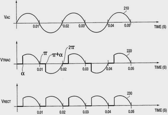
This is the circuit diagram of the simplest lamp dimmer or fan regulator.The circuit is based on the principle of power control using a Triac.The circuit works by varying the firing angle of the Triac . Resistors R1 ,R2 and capacitor C2 are associated with this. The firing angle can be varied by varying the value of any of these components. Here R1 is selected as the variable element . By varying the value of R1 the firing angle of Triac changes (i.e. how much time should Triac conduct) changes. This directly varies the load power, since load is driven by Triac. The firing pulses are given to the gate of Triac T1 using Diac D1. The most basic wavefor(i.e ignoring all losses and harmonics) is shown below.


The waveform shown below demonstrates the output voltage of TRIAC before and after rectification.
Alpha is firinf angel of thyristers.


From the two figures shown below  we can see the output waveform by changing firing angel. In the first figure  the output will be half power of the input power.
In the second figure as firing angel is zero ,therefore output power will be same as input.


The Thing


There is a diaphram in the eye of eagle which get vibrated when sound wave fall on it . It consisted of a tiny capacitive membrane connected to a small quarter-wavelength antenna; it had no power supply or active electronic components. The device became active only when a radio signal of the correct frequency was sent to the device from an external transmitter. 


Sound waves caused the membrane to vibrate, which varied the capacitance of the circuit.When capacitance get changed , operating frequency get changed.When this changed frequency supply reached Antenna circuit, different EM wave is produced which get modulated with incoming EM wave and is get re-transmitted by the Thing. A receiver demodulated the signal so that sound picked up by the microphone could be heard, just as an ordinary radio receiver demodulates radio signals and outputs sound.

Q Factor


The Q, quality factor, of a resonant circuit is a measure of the goodness or quality of a resonant circuit. A higher value for this figure of merit correspondes to a more narrow bandwith, which is desirable in many applications. More formally, Q is the ration of power stored to power dissipated in the circuit reactance and resistance.  


Series Resonance

The resonance of a series RLC circuit occurs when the inductive and capacitive reactances are equal in magnitude but cancel each other because they are 180 degrees apart in phase. The sharp minimum in impedance which occurs is useful in tuning applications. The sharpness of the minimum depends on the value of R and is characterized by the "Q" of the circuit.

The frequency response of the circuits current magnitude above, relates to the “sharpness” of the resonance in a series resonance circuit. The sharpness of the peak is measured quantitatively and is called the Quality factor, Q of the circuit. The quality factor relates the maximum or peak energy stored in the circuit (the reactance) to the energy dissipated (the resistance) during each cycle of oscillation meaning that it is a ratio of resonant frequency to bandwidth and the higher the circuit Q, the smaller the bandwidth. 


Parallel Resonance
The Q-factor of a parallel resonance circuit is the inverse of the expression for the Q-factor of the series circuit. Also in series resonance circuits the Q-factor gives the voltage magnification of the circuit, whereas in a parallel circuit it gives the current magnification.
The selectivity or Q-factor for a parallel resonance circuit is generally defined as the ratio of the circulating branch currents to the supply current and is given as: 


The Q-factor of a parallel resonance circuit is the inverse of the expression for the Q-factor of the series circuit. Also in series resonance circuits the Q-factor gives the voltage magnification of the circuit, whereas in a parallel circuit it gives the current magnification


Resonant circuits are used to respond selectively to signals of a given frequency while discriminating against signals of different frequencies. If the response of the circuit is more narrowly peaked around the chosen frequency, we say that the circuit has higher selectivity. A quality factor Q, is a measure of that selectivity, and we speak of a circuit having a high Q if it is more narrowly selective. 
An example of the application of resonant circuits is the selection of AM radio stations by the radio receiver. The selectivity of the tuning must be high enough to discriminate strongly against stations above and below in carrier frequency, but not so high as to discriminate against the "sidebands" created by the imposition of the signal by amplitude modulation. 

Consider a circuit where R, L and C are all in parallel. The lower the parallel resistance, the more effect it will have in damping the circuit and thus the lower the Q.

Radar


A radar system has a transmitter that emits radio waves called radar signals in predetermined directions. When these come into contact with an object they are usually reflected or scattered in many directions. Radar signals are reflected especially well by materials of considerable electrical conductivityespecially by most metals, by sea water and by wet lands. The radar signals that are reflected back towards the transmitter are the desirable ones that make radar work. If the object is moving either toward or away from the transmitter, there is a slight equivalent change in the frequency of the radio waves, caused by the Doppler effect.

If electromagnetic waves traveling through one material meet another, having a very different dielectric constant or diamagnetic constant from the first, the waves will reflect or scatter or refract  from the boundary between the materials. This means that a solid object in air or in a vacuum, or a significant change in atomic density between the object and what is surrounding it, will usually scatter radio waves from its surface.
Radar receivers are usually, but not always, in the same location as the transmitter. Although the reflected radar signals captured by the receiving antenna are usually very weak, they can be strengthened by electronic amplifiers.

There are basically two types of radar:

1) Primary radar
2) Secondary radar

Primary radar has lots of limitations. It works best with large all-metal aircraft, not so well on small, composite aircraft, and not at all with some of the new "stealth" technology. Its range is limited by terrain and precipitation. It's rather indiscriminite about what it detects: airplanes, trucks, hills, trees. And it only reports a target's  and range, not its altitude (only 2D).

Secondary radar was invented to overcome these limitations. It depends on a transponder in the aircraft to respond to interrogations (type of signal) from the ground station. Depending on the type of interrogation, the transponder sends back an identification code  or altitude information.


Radar ground stations:

 It consist of three separate antennas. The biggest  one is the primary radar antenna, which looks like a parabolic dish that goes round and round . This antenna transmits powerful pulses and then listens for echoes. It is used to detect aircraft skin paint and also can detect weather to some degree. 
The second ground station antenna, called the directional antenna, is used to send interrogations to airborne transponders and to receive replies from those transponders, providing secondary radar capability. It is a bar-shaped  that is usually perched atop the primary radar antenna and rotates along with it. It's called directional because, like the primary radar antenna, it is designed to beam the interrogations and to receive the replies only from the direction it is pointed. 
However, the directional antenna is less than perfectly directional. To design a perfectly directional antenna, we have to make it infinitely large and thus not practical . Real-world directional antennas have weaker side lobes in addition to the main lobe. The side lobes are too weak to be a problem for distant aircraft, but for aircraft close to the antenna site they are a big problem. Unless something was done about them, the side lobes would cause a close-in aircraft to show up as three or four different targets on the controller's screen, causing  confusion.

Side lobe supression:

That's where the third antenna comes in. It's called the omnidirectional antenna because it radiates equally in all directions. Every time the directional antenna sends out an interrogation (which consists of a pair of pulses), the omnidirectional antenna sends out its own pulse . The signal from the omnidirectional antenna is designed to be much weaker than the main lobe of the directional antenna, but stronger than its side lobes. 

When the transponder receives an interrogation, it compares the strength of the three pulses it receives and according to the strength of the signals it provides information. 

Magnetron


All cavity magnetrons consist of a  cathode with a high (continuous or pulsed) negative potential created by a high-voltage, direct-current power supply. The cathode is built into the center of an evacuated, lobed, circular chamber. A magnetic field parallel to the filament is imposed by a permanent magnet. The magnetic field causes the electrons, attracted to the (relatively) positive outer part of the chamber, to spiral outward in a circular path, a consequence of the Lorentz force. Spaced around the rim of the chamber are cylindrical cavities. The cavities are open along their length and connect the common cavity space. As electrons sweep past these openings, they induce a resonant, high-frequency radio field in the cavity, which in turn causes the electrons to bunch into groups. This principle of cavity resonator is very similar to blowing a stream of air across the open top of a glass pop bottle. A portion of the field is extracted with a short antenna that is connected to a waveguide .The waveguide directs the extracted RF energy to the load, which may be a cooking chamber in a microwave oven or a high-gain antenna in the case of radar.


The magnetron is called a "crossed-field" device in the industry because both magnetic and electric fields are employed in its operation, and they are produced in perpendicular directions so that they cross. The applied magnetic field is constant and applied along the axis of the circular device illustrated. The power to the device is applied to the center cathode which is heated to supply energetic electrons which would, in the absence of the magnetic field, tend to move radially outward to the ring anode which surrounds it.
  
Electrons are released at the center  cathode by the process of thermionic emission and have an accelerating field which moves them outward toward the anode. The axial magnetic field exerts a magnetic force on these charges which is perpendicular to their initially radial motion, and they tend to be swept around the circle. In this way, work is done on the charges and therefore energy from the power supply is given to them. As these electrons sweep toward a point where there is excess negative charge, that charge tends to be pushed back around the cavity, imparting energy to the oscillation at the natural frequency of the cavity. This driven oscillation of the charges around the cavities leads to radiation of electromagnetic waves, the output of the magnetron.

The sizes of the cavities determine the resonant frequency, and thereby the frequency of emitted microwaves. However, the frequency is not precisely controllable. The operating frequency varies with changes in load impedance, with changes in the supply current, and with the temperature of the tube. This is not a problem in uses such as heating, or in some forms of radar where the receiver can be synchronized with an imprecise magnetron frequency. Where precise frequencies are needed, other devices such as the klystron are used.

The magnetron is a self-oscillating device requiring no external elements other than a power supply. A well-defined threshold anode voltage must be applied before oscillation will build up; this voltage is a function of the dimensions of the resonant cavity, and the applied magnetic field. In pulsed applications there is a delay of several cycles before the oscillator achieves full peak power, and the build-up of anode voltage must be synchronized with the build-up of oscillator output.
  

The magnetron is a fairly efficient device. In a microwave oven, for instance, a 1.1 kilowatt input will generally create about 700 watts of microwave power, an efficiency of around 65%. (The high-voltage and the properties of the cathode determine the power of a magnetron.).

Mag Flowmeter


Magnetic flowmeters use Faradays Law of Electromagnetic Induction to determine the flow of liquid in a pipe. In a magnetic flowmeter, a magnetic field is generated and channeled into the liquid flowing through the pipe. Following Faradays Law, flow of a conductive liquid through the magnetic field will cause a voltage signal to be sensed by electrodes located on the flow tube walls. When the fluid moves faster, more voltage is generated. Faradays Law states that the voltage generated is proportional to the movement of the flowing liquid. The electronic transmitter processes the voltage signal to determine liquid flow.

A magnetic flow meter (mag flowmeter) is a volumetric flow meter which does not have any moving parts and is ideal for wastewater applications or any dirty liquid which is conductive or water based. Magnetic flowmeters will generally not work with hydrocarbons, distilled water and many non-aqueous solutions). Magnetic flowmeters are also ideal for applications where low pressure drop and low maintenance are required.

Principle of Operation

The operation of a magnetic flowmeter or mag meter is based upon Faraday's Law, which states that the voltage induced across any conductor as it moves at right angles through a magnetic field is proportional to the velocity of that conductor.

Faraday's Formula:

E is proportional to V x B x D where:

E = The voltage generated in a conductor
V = The velocity of the conductor
B = The magnetic field strength
D = The length of the conductor

 To apply this principle to flow measurement with a magnetic flowmeter, it is necessary first to state that the fluid being measured must be electrically conductive for the Faraday principle to apply. As applied to the
design of magnetic flowmeters, Faraday's Law indicates that signal voltage (E) is dependent on the average liquid velocity (V) the magnetic field strength (B) and the length of the conductor (D) (which in this instance is the distance between the electrodes). 


Magnetic flowmeters measure the velocity of conductive liquids in pipes, such as water, acids, caustic, and slurries.However fluids with low conductivity, such as de-ionized water, boiler feed water, or hydrocarbons, can cause the flowmeter to turn off and measure zero flow.
This flowmeter does not obstruct flow, so it can be applied to clean, sanitary, dirty, corrosive and abrasive liquids. Magnetic flowmeters can be applied to the flow of liquids that are conductive, so hydrocarbons and gases cannot be measured with this technology due to their non-conductive nature and gaseous state respectively.